I2C Overview
I2C (Inter-Integrated Circuit) Protocol :
OVERVIEW:
- I2c stands for the inter-integrated circuit (developed by Philips nxp)
- This comes under the intra communication protocol.
- I2C allows up to 100Kbps in the standard mode and 400Kbps in a fast
mode. - A very commonly used low-speed bus to connect the onboard devices to processor.
- It supports two wires:
- SCL (Serial clock/synchronous clock)
- SDA (Serial Data ) TX/RX
- This protocol supports synchronous serial communication.
- it supports half-duplex communication
- it is master/slave bus: the only master can initiate the transaction, slave only reply to a transaction initiated by the master.
- In a Linux system, the i2c controller embedded in the processor is typically the master, controlling the bus.
- I2C follows addressing mechanisms.
- Each salve devices is identified by a unique i2c address. Each transaction initiated by the master contains this address, which allows the relevant slave to recognize that it should reply to this particular transaction.
- I2c support multi-master communication.
- i2c support two modes:
- 7-bit mode.( maximum of 127 devices on the bus )
- 10-bit mode.
- Benefits for i2c subsystem:
- hardware complexity is less.
- In the I2c subsystem, the master can communicate with one slave at a time.
Addressing Mechanism:
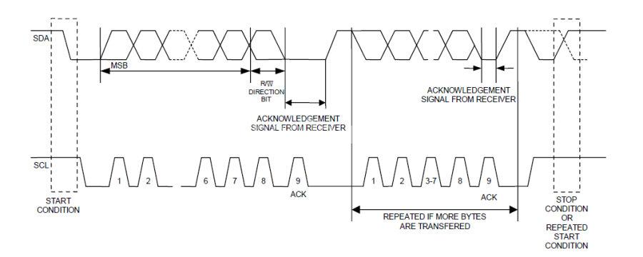
- Every time master should initiate the communication by achieving the start condition.
- In I2c, the master sends the data (8bit ) in the form of the packets in which the upper 7 bit is the slaved address and 8th is the control bit for reading or writing from/to devices
- (write=0 read=1 )
- Then the slave sends the ACK and master read that ACK bit, then master knows that communication is done.
- Each i2c command initiated by master drives start with a START condition and end with A STOP condition.
- For both conditions, SCL has to be high.
- A high to low transition of the SDA is considered a START.
- A Low to High transition of the SDA is considered as STOP.
Data transaction:
- Master must generate its own clock signal and data present only when the clock is low.

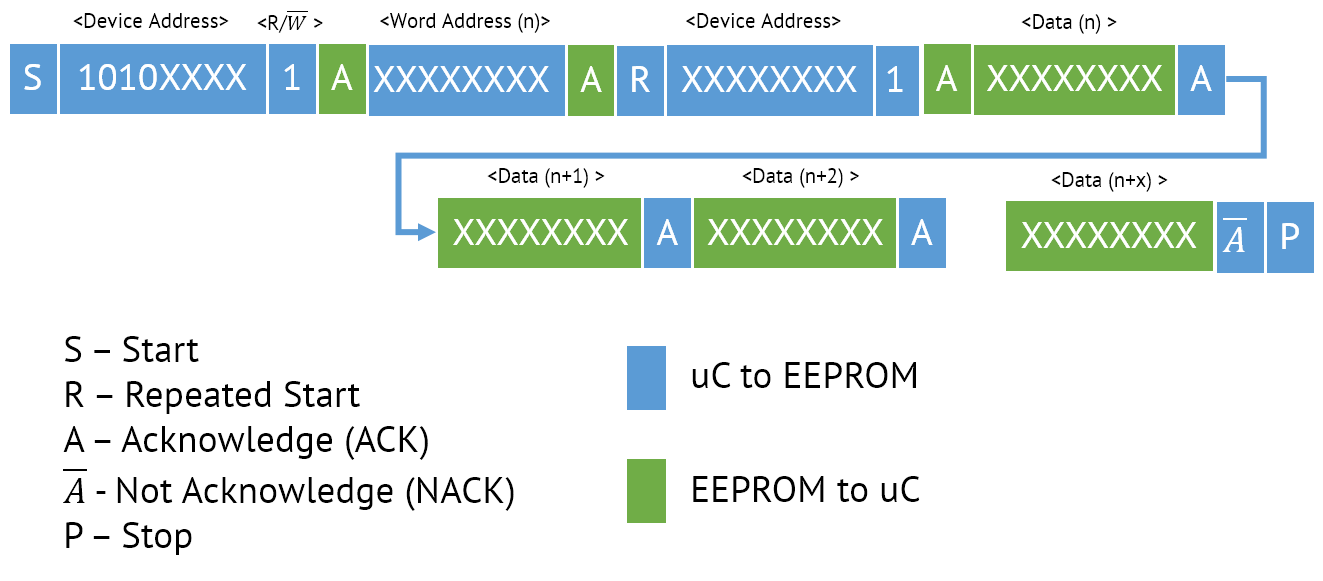
Repeated start
Arbitration:
several I2C multi-master can be connected to the same I2C bus and operate concurrently. By constantly monitoring SDA and SCL for start and stop conditions, they can determine whether the bus is currently idle or not. If the bus is busy, masters delay pending I2C transfers until a stop condition indicates that the bus is free again.However, it may happen that two masters start a transfer at the same time. During the transfer, the masters constantly monitor SDA and SCL. If one of them detects that SDA is low when it should actually be high, it assumes that another master is active and immediately stops its transfer. This process is called arbitration
I2C – Clock Stretching
- In I2C communication, the master device determines the clock speed
- However, there are situations where an I2C slave is not able to co-operate with the clock speed given by the master and needs to slow down a little
- This is done by a mechanism referred to as clock stretching
- An I2C slave is allowed to hold down the clock if it needs to reduce the bus speed. The master on the other hand is required to read back the clock signal after releasing it to a high state and wait until the line has actually gone high.
I2C Device Driver:
- I2C and SMBus are master-slave protocols where communication takes place between a host adapter (or host controller) and client devices (or slaves)
I2C core:
- The I2C core is a codebase consisting of routines and data structures available to host adapter drivers and client drivers.
- Common code in the core makes the driver developer's job easier.
- The core also provides a level of indirection that renders client drivers independent of the host adapter, allowing them to work unchanged even if the client device is used on a board that has a different I2C host adapter
along with I2c core, Kernel I2c infrastructure consists of
- aThe device driver of the I2c adapter.
- Device driver for the I2c client device.
- I2c dev, which allows the implementation of user mode I2C client drivers

Writing the I2C client Driver:
An I2C driver is represented in the kernel as an instance of struct i2c_driver. The I2C
client (which represents the device itself) is represented by a struct i2c_clientstructure.
An I2C driver is declared in kernel as an instance of struct i2c_driver,
struct i2c_driver {
int (*probe)(struct i2c_client *, const struct i2c_device_id *);
int (*remove)(struct i2c_client *);
struct device_driver driver;
const struct i2c_device_id *id_table;
};
struct i2c_driver structure contains and characterizes general access routines
needed to handle the devices claiming the driver, whereas struct i2c_client contains
device-specific information, such as its address.
probe() function:
- Check whether the device is the one you expected
- Check whether your I2C bus controller of the SoC supports the functionality needed by your device, using the i2c_check_functionality function
- Initialize the device
- Set up device-specific data
- Register the appropriate kernel framework
Probe function prototype:
- static int ds1307_probe(struct i2c_client *client, const struct i2c_device_id *id);
struct i2c_client pointer: This represents the I2C device itself
struct i2c_client
{
unsigned short addr; /* chip address - NOTE: 7 bit */
/* addresses are stored in the *//* _LOWER_ 7 bits */
char name[I2C_NAME_SIZE];
struct i2c_adapter *adapter;
/* the adapter we sit on */
struct device dev; /* the device structure */
intirq; /* IRQ issued by device */
struct list_head detected;
#if IS_ENABLED(CONFIG_I2C_SLAVE)
#if IS_ENABLED(CONFIG_I2C_SLAVE)
i2c_slave_cb_t slave_cb; /* callback for slave mode */
#endif
respects that principle. I2C core provides two kinds of API, one for plain I2C
communications and another for SMBUS-compatible devices, which also works with I2C
devices but not the reverse
};
- struct i2c_device_id pointer: This points to the I2C device ID entry that
matched the device that is being probed.
Remove function:
static int foo_remove(struct i2c_client *client;
The remove function has the responsibility to unregister us from the subsystem where we
registered in the probe() function
Driver initialization and registration :
module_i2c_driver(foo_driver);
Driver and device provisioning :
we need to provide a device_id array in order to expose devices that our driver can manage.
Since we are talking about I2C devices, the structure would be i2c_device_id
static const struct i2c_device_id ds1307_id[] = {
{ "ds1307", ds_1307 },
{ "ds1337", ds_1337 },
{ }
};
MODULE_DEVICE_TABLE(i2c, ds1307_id);
struct i2c_device_id {
char name[I2C_NAME_SIZE];
kernel_ulong_t driver_data; /* Data private to the driver */
};
static struct i2c_driver ds1307_driver = {
.driver = {
.name = "rtc-ds1307",
},
.probe = ds1307_probe,
.remove = ds1307_remove,
.id_table = ds1307_id,
};
module_i2c_driver(ds1307_driver);
MODULE_DESCRIPTION("RTC driver for DS1307 and similar chips");
MODULE_LICENSE("GPL");
Accessing the client
Serial bus transactions are just a matter of accessing registers to set/get their content. I2Crespects that principle. I2C core provides two kinds of API, one for plain I2C
communications and another for SMBUS-compatible devices, which also works with I2C
devices but not the reverse
Plain I2C communication
- int i2c_master_send(struct i2c_client *client, const char *buf, int count);
- int i2c_master_recv(struct i2c_client *client, char *buf, int count);
- int i2c_transfer(struct i2c_adapter *adap, struct i2c_msg *msg,int num);
System Management Bus (SMBus) compatible functions
- extern s32 i2c_smbus_read_byte(const struct i2c_client *client); Reads a single byte from the device without specifying a location offset. Uses the same offset as the previously issued command.
- extern s32 i2c_smbus_write_byte(const struct i2c_client *client, u8 value); Sends a single byte to the device at the same memory offset as the previously issued command.
- extern s32 i2c_smbus_read_byte_data(const struct i2c_client *client,u8 command); Reads a single byte from the device at a specified offset.
- extern s32 i2c_smbus_write_byte_data(const struct i2c_client *client,u8 command, u8 value); Sends a single byte to the device at a specified offset.
- extern s32 i2c_smbus_read_word_data(const struct i2c_client *client,u8 command); Reads 2 bytes from the specified offset.
- extern s32 i2c_smbus_write_word_data(const struct i2c_client *client, u8 command, u16 value);Sends 2 bytes to the specified offset.
- extern s32 i2c_smbus_read_block_data(const struct i2c_client *client,u8 command, u8 *values); Reads a block of data from the specified offset.
- extern s32 i2c_smbus_write_block_data(const struct i2c_client *client,u8 command, u8 length, const u8 *values); Sends a block of data (<= 32 bytes) to the specified offset.
Sample Dtb file : sample DTB file
Header files:
- linux/include/linux/i2c.h
- include/linux/mod_devicetable.h
- include/uapi/linux/i2c.h
- drivers/i2c/i2c-core.c
- drivers/rtc/rtc-ds1307.c
Interview Question
- What is the difference between I2C & SPI
- How will you choose which protocol to be used onboard communication?
- How the communication difference b/w I2C & SPI
- Is clock stretching is for Master or Slave in I2C protocol
- What is Bit Binding in I2C protocol?
- As the controller pin muxing, we may get the I2c pins for actually I2c data communication. so in that case we can use the Normal Gpios pins are I2c pins and we can implement the I2c protocol.
- What is the i2c clock stretching ?
- in the real-time scenarios, the slave device will have low processing time for data. To avoid data loss, slave devices will strecting the clock. will process the data and after processing complete it will release the clock pin.
- what is a repeated sequence in I2C? How this signal will look on CRO?
- How will you know if the I2C lines are noisy?
- What monitoring tools have you used like I2C sniffer
- how will you verify I2C communication? How will you know if there was a software or hardware problem?
- what is i2c bus error?
- I2C- dummy write, repeated start, arbitration, synchronization between masters
- Lm475 temperature driver project
- How can two slaves can communicate with a master in i2c protocol at a time?
- How can we address different devices from the same vendor i2c?
- What is the clock frequency used in your I2C driver designed?
- What is the start bit condition in I2C?
- How the I2C protocol works?
- What are the different speeds the I2C had?
- How the master knows what is the start condition?
- while in between I2C communication what happens if clocks happen to be dragged low which is not as per i2c standard?
- What if the slave device is not responding or no acknowledge bit is sent by the slave device?
- what is I2C Clock Stretch, Bus line clear?
- When 2 or 3 clients application try to access the bus at the same time? how can you resolve this issue?


Comments
Post a Comment